Support Blog
GPIO Interfacing for J4220UX, J4212U and J4224

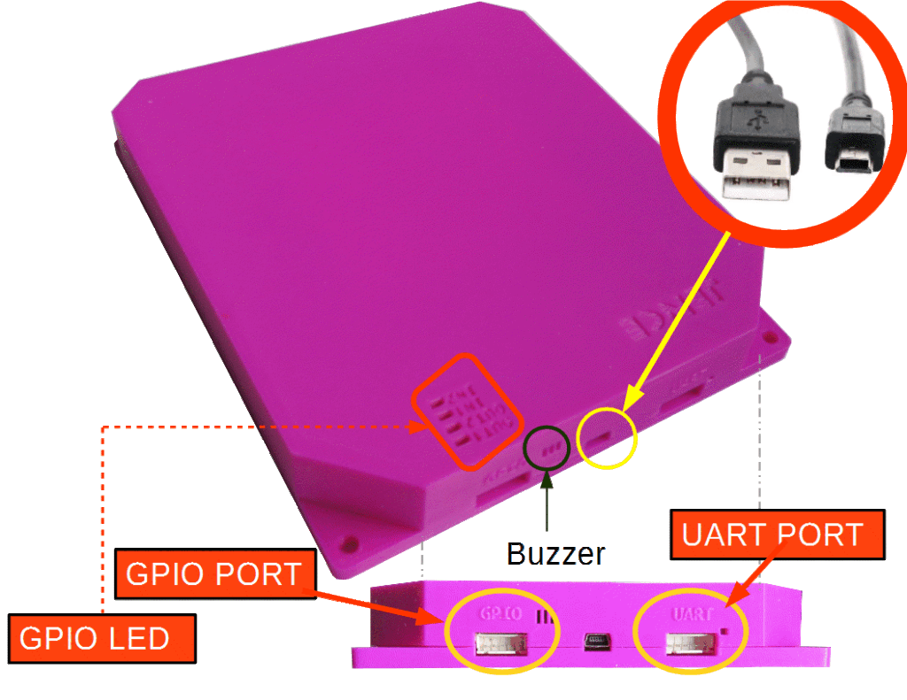
GPO1 and GPO2 – Active Low Open Drain. Must provide at pullup resistor. Maximum continuous load current 35mA.
GPI1 and GPI2 – High Impedance input.
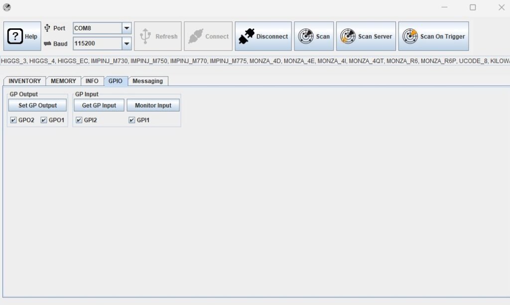
In the J4210U app inside the GPIO tab, there are two options: GP Output and GP Input.
GP Input:
If we connect Input 1 pin to the Ground and press Monitor Input Button, GPI2 will be checked automatically and in the hardware Led in IN2 will light up.


If we connect Input 2 pin to the Ground and press Monitor Input Button, GPI1 will be checked automatically and in the hardware Led in IN1 will light up.
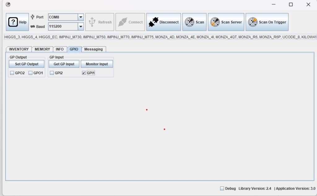
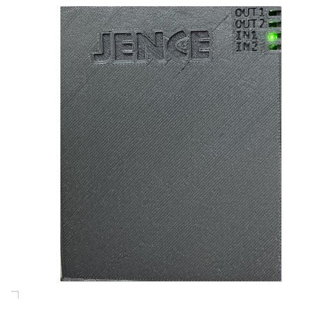
If we do not connect any input pins to the Ground and press Monitor Button, Both GPI1 and GPI2 will be checked automatically and in the hardware Led in both In1 and In2 will light up.
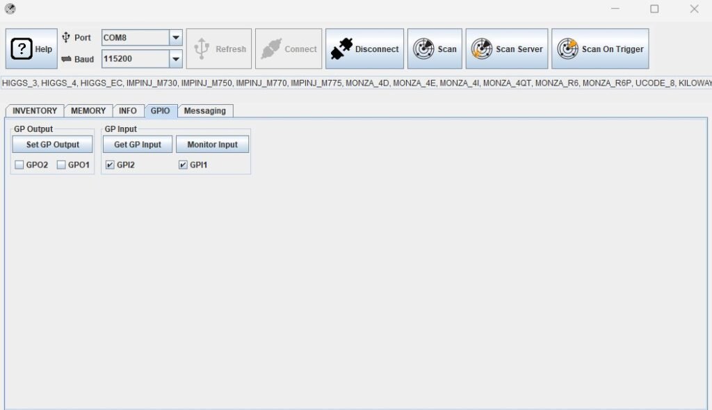
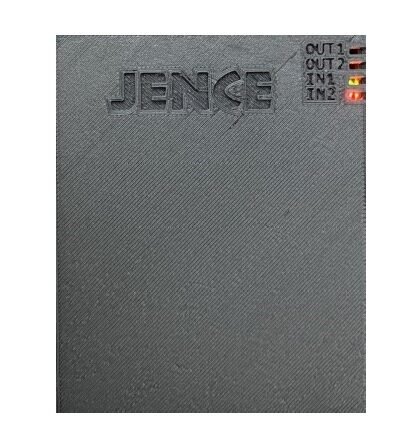
GP Output:
If we select GPO1 and press Set GP Output button, the led in OUT1 will light up.
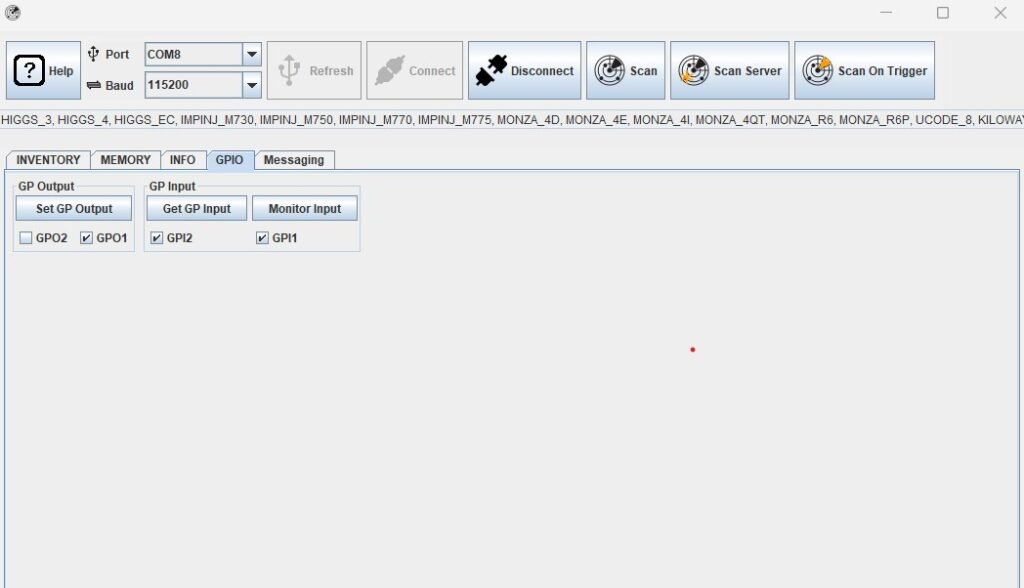
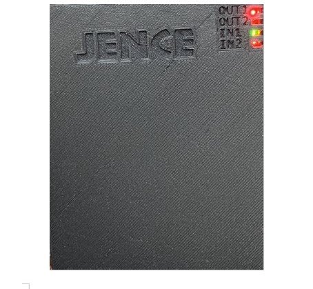
If we select GPO2 and press Set GP Output button, the led in OUT2 will light up.


If we select both GPO1 and GPO2 and press Set GP Output button, the led in both OUT1 and OUT2 will light up.
