
Support Blog
Automated RFID Gate using Python With Raspberry Pi & JENCE UHF Readers

Sep
Integrating long-range UHF RFID readers with single-board computers like the Raspberry Pi provides a robust, industrial-grade foundation for physical security, automated vehicle barrier gates, intelligent parking management systems, and smart factory access control. While standard high-frequency (HF 13.56 MHz) or NFC card readers require close proximity contact, ultra-high frequency (UHF 860 MHz – 960 MHz) RFID systems can detect passive EPC tags at long range—making them the industry standard for hands-free vehicle identification and automatic gate triggering.
In this comprehensive technical guide, we will transform a Raspberry Pi and a high-performance JENCE J4212U (or JENCE J4220U Long Range Reader) into a complete, standalone automated gate access control system. Instead of relying on a manual desktop GUI app, we will deploy an event-driven Python script running directly in the terminal. The script maintains a continuous background inventory scanning loop, evaluates incoming EPC Class 1 Gen 2 (ISO 18000-6C) tags against an authorized database, and directly triggers the JENCE reader’s integrated General Purpose Output (GPO) pins to activate an external relay module and drive a motorized barrier gate. [You can also find this Project in Instructables]
Subscribe to our newsletter :
System Architecture and Engineering Principles
A primary challenge in long-range RFID gate automation is bridging low-voltage microcontroller logic with high-current electro-mechanical equipment. This tutorial utilizes a decoupled hardware architecture that isolates high-current inductive motor spikes from the sensitive microprocessing core of the Raspberry Pi.
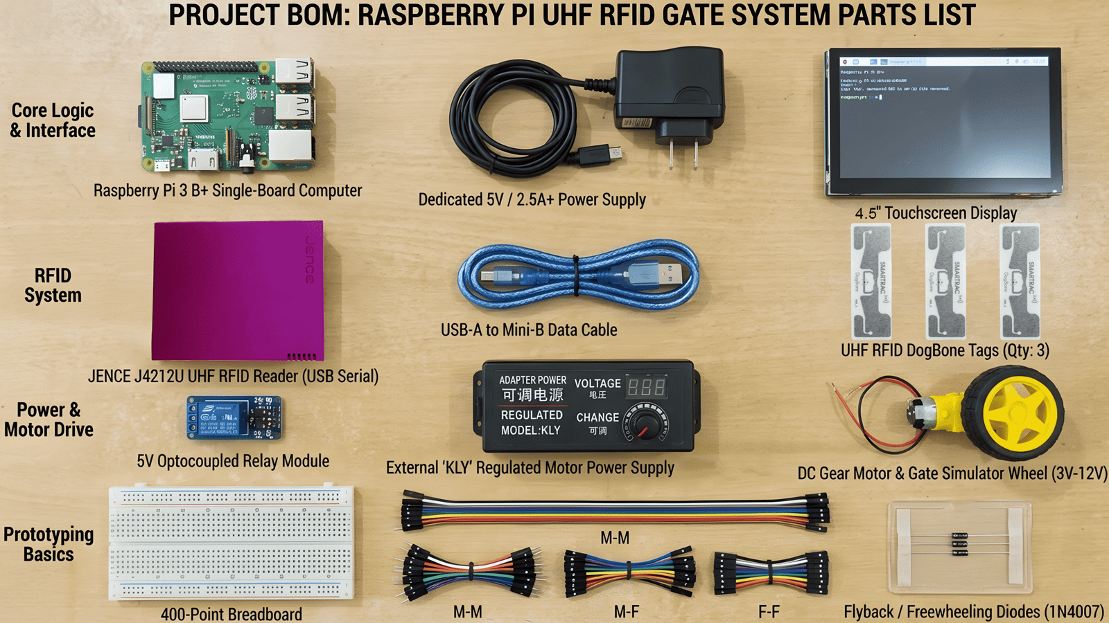
Supplies
Core Components and Hardware Specifications:
- Raspberry Pi Single-Board Computer:
- Compatibility: Fully compatible with Raspberry Pi 3 B+(Used in this Project), Pi 4, Pi 5, or Pi Zero 2 W running either 32-bit or 64-bit Raspberry Pi OS (formerly Raspbian).
- Role: Acts as the main application host executing the custom Python control script via terminal.
- Power Supply: Requires a dedicated 5V / 2.5A+ power supply to ensure stable operation during continuous USB serial communication.
- JENCE UHF RFID Reader Module:
- Recommended Hardware: The JENCE J4220U Long Range Reader for long-distance vehicle access control (up to 12+ meters)[Available on Amazon], or the compact JENCE J4212U Reader/Writer for desktop prototyping and short-range testing [Available on Amazon] (We have mainly used JENCE J4212U Reader/Writer for this Project).
- Communication Interface: Operates over standard USB-to-UART serial protocol using a high-speed USB-A to Mini-B cable.
- 5V Optocoupled Relay Module (Active High Trigger):
- Function: Acts as an electrically isolated switch to complete the high-current DC motor circuit when a trigger logic signal is received.
- Control Inputs: VCC, GND, and IN (Signal Input).
- External Motor Power Supply & DC Motor (Gate Simulator):
- Power Source: An external adjustable power adapter or battery dedicated solely to driving the gate motor load. (Warning: Never draw motor power directly from the Raspberry Pi or JENCE Reader headers, as reverse EMF and current draw will trigger low-voltage warnings or destroy the logic board).
- Motor: A 3V–12V DC gear motor simulating a motorized sliding gate, turnstile, or parking barrier arm.
- Flyback / Freewheeling Diode (1N4007 or similar):
- Protection: Placed in reverse parallel across the motor terminals (cathode to positive, anode to negative) to suppress inductive voltage spikes (Back-EMF) generated when the relay opens and closes.
- UHF RFID Tags:
- Quantity & Model: 3+ pcs (DogBone tags recommended for maximum range; 3 tags are included directly in the J4212U and J4220U package) [Also Available in RFDOME Store and Amazon].
- Hook-up Wires / Jumpers:
- Quantity & Types: As needed (standard jumper wires including male-to-female, female-to-female, and male-to-male).
- Breadboard (Optional):
- Quantity: 1 pc (used for quick circuit distribution and prototyping).
Hardware Wiring & Interconnection Guide
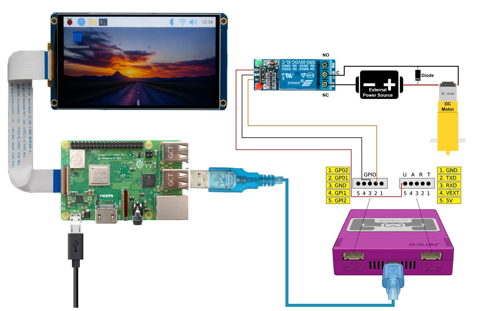
Full Project Diagram
The key innovation in this design is leveraging the JENCE Reader’s dedicated GPO (General Purpose Output) terminal header, rather than consuming the Raspberry Pi’s GPIO pins. This reduces wiring clutter at the host controller, minimizes logic latency, and simplifies hardware deployment at physical entry points.
Refer to Full Project Diagram above for wiring verification:
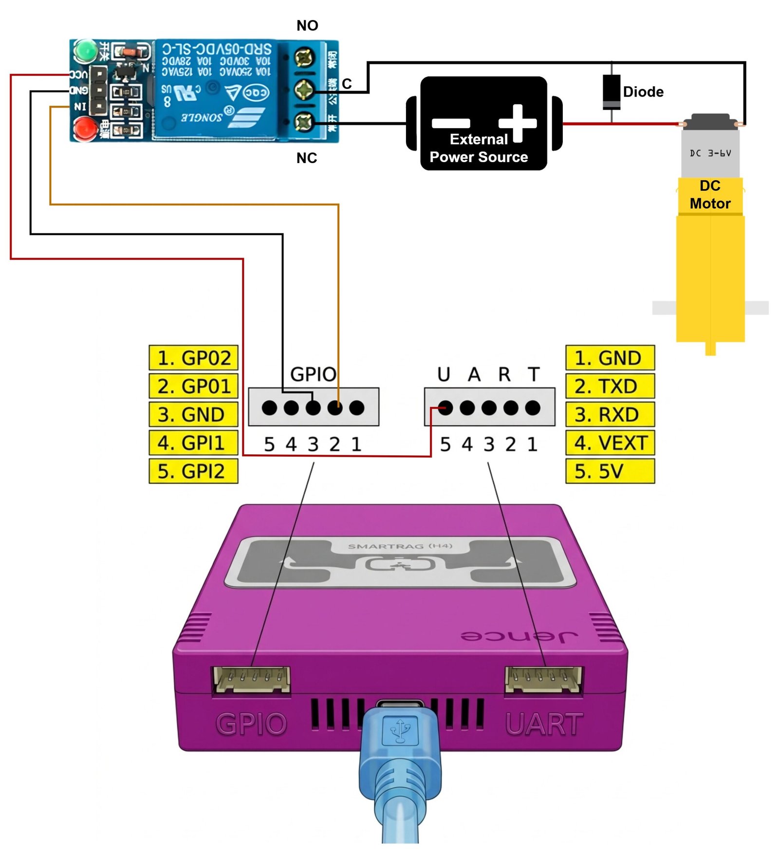
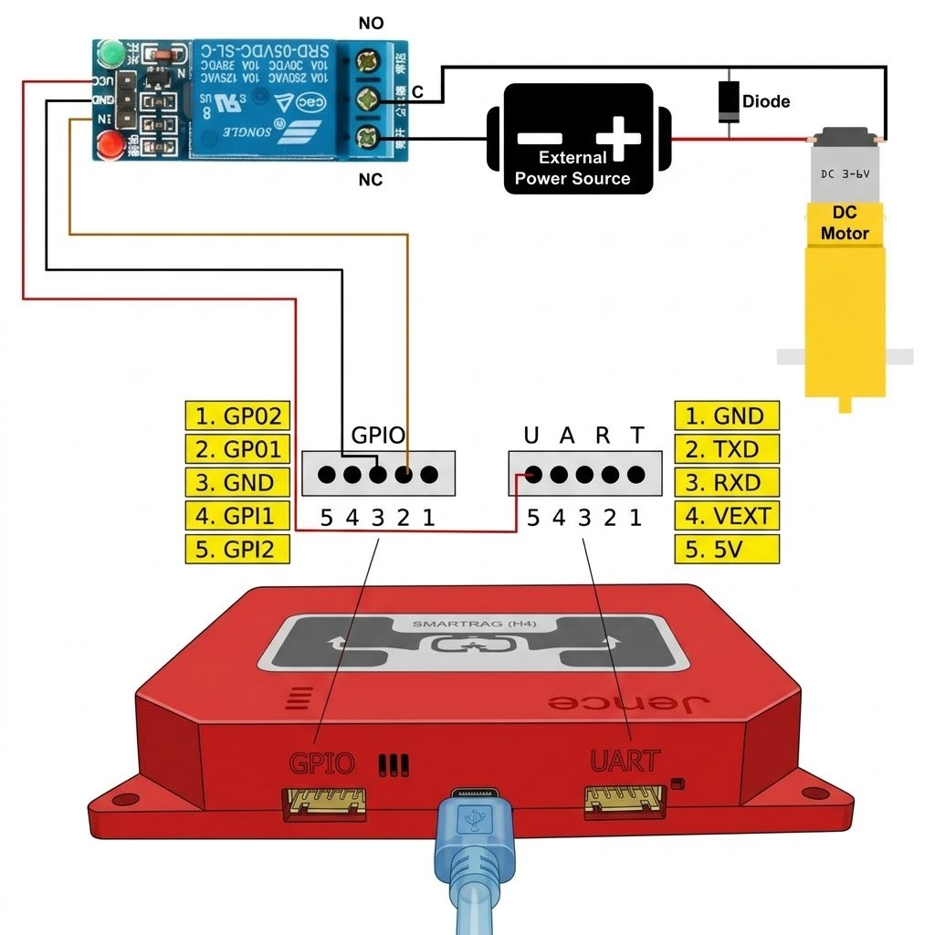
A. Control Signal Wiring (JENCE Reader to 5V Relay Module)
- VCC (Relay Board) → 5V Power Output (JENCE UART Header Pin 5): Supplies the 5V operational power needed to energize the relay’s internal coil.
- GND (Relay Board) → GND (JENCE GPIO Header Pin 3): Establishes a common ground reference between the JENCE logic outputs and the relay board.
- IN / Signal (Relay Board) → GP01 (JENCE GPIO Header Pin 2): The primary digital trigger signal line. When authorized tags are identified, the Python application drives this pin HIGH (+5V), switching the relay state.
B. Load Circuit Wiring (Relay to External Power Supply and DC Motor)
- External Power Supply (+) Positive Lead → Motor Terminal 1: Connects positive voltage directly to the DC motor.
- External Power Supply (-) Negative Lead → Relay Normally Closed (NC) Terminal: The ground return line connects to the relay’s NC terminal.
- Relay Common (C) Terminal → Motor Terminal 2: Completes the negative ground loop when the relay coil is activated. (Note: While high-side positive switching is common, breaking the low-side negative ground leg through the relay NC/C terminals functions identically and is fully supported).
- Flyback Protection Diode: Solder or connect a 1N4007 diode across Motor Terminal 1 and Motor Terminal 2, ensuring the silver cathode band faces the positive supply rail.
Software Preparation & Dependencies
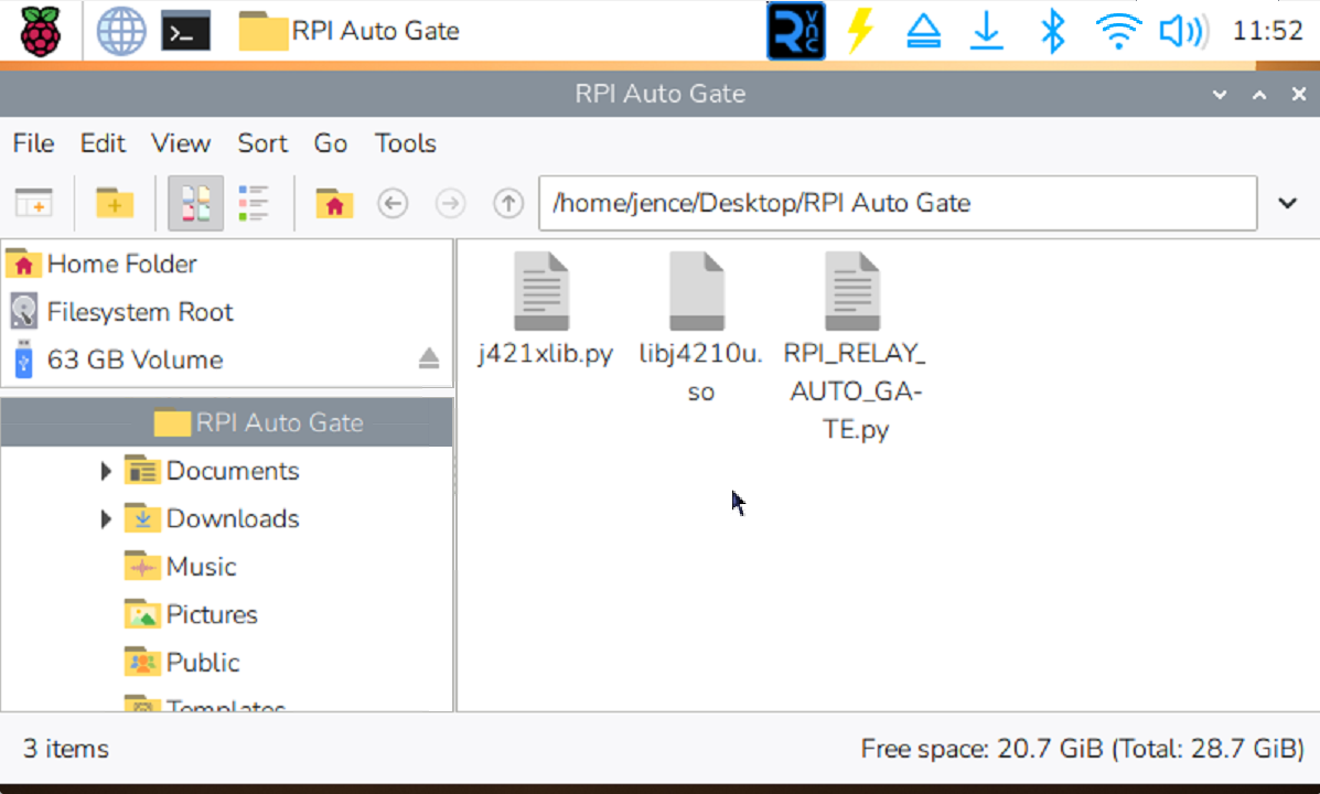
Project Folder and it’s Contents
This automated gate controller runs as a headless Python application from the Linux terminal. Because Python provides cross-platform hardware abstraction, this project runs smoothly on both 32-bit and 64-bit Raspberry Pi OS distributions.
Step 1: Operating System and Dependency Setup
Open a terminal session on your Raspberry Pi (or connect via SSH) and update system packages, then install Python 3, Pip, and the pyserial communications library:
sudo apt update && sudo apt upgrade -y

sudo apt install python3 python3-pip python3-pyserial -y
Step 2: Project Files and Directory Structure
To run the automated gate application, three specific files must reside together within the same project directory on your Raspberry Pi. Download the project ZIP archive from the provided Google Drive directory and extract its contents:
/home/pi/RPI_AUTO_GATE/

RPI_RELAY_AUTO_Gate.py # Primary executable terminal script

j421xlib.py # Python wrapper library for JENCE C-SDK

libj4210u.so # Native compiled binary driver (.so shared library)
Module Architecture Explained:
- RPI_RELAY_AUTO_Gate.py (Main Application): Contains the main application loop, terminal serial port selection prompt, continuous EPC tag polling logic, hardcoded authorization verification array, and GPO trigger timing routines.
- j421xlib.py (Python SDK Wrapper): Imports low-level C functions from libj4210u.so into high-level, human-readable Python functions such as OpenPort(), Inventory(), and SetGPO().
- libj4210u.so (Compiled C/C++ Shared Library): The underlying low-level binary compiled specifically to handle direct, high-speed USB-to-Serial packet parsing, CRC checking, and register manipulation on JENCE UHF hardware.
You can download the full Open Source SDK for JENCE UHF RFID Readers to integrate your hardware with any of the supported platforms below:
- Android
- Arduino
- Banana Pi
- BeagleBone / BeagleBone AI-64
- Linux (64-bit)
- macOS / macOS (Intel)
- Node.js
- Orange Pi
- PocketBeagle
- Python 3
- Raspberry Pi (32-bit & 64-bit)
- Windows (32-bit & 64-bit)
Software Download: Download the open-source SDK and Demo App from the JENCE GitHub repository: https://github.com/jence/j4210u-app
Python Script Execution & Workflow Logic
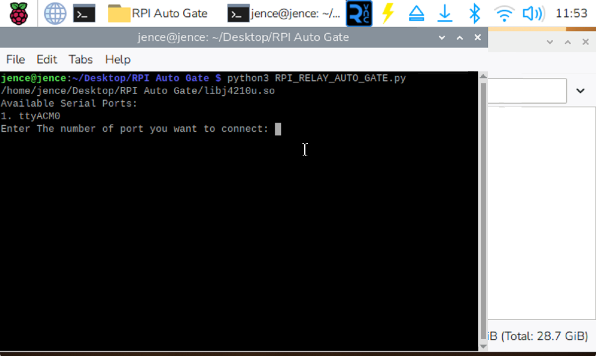
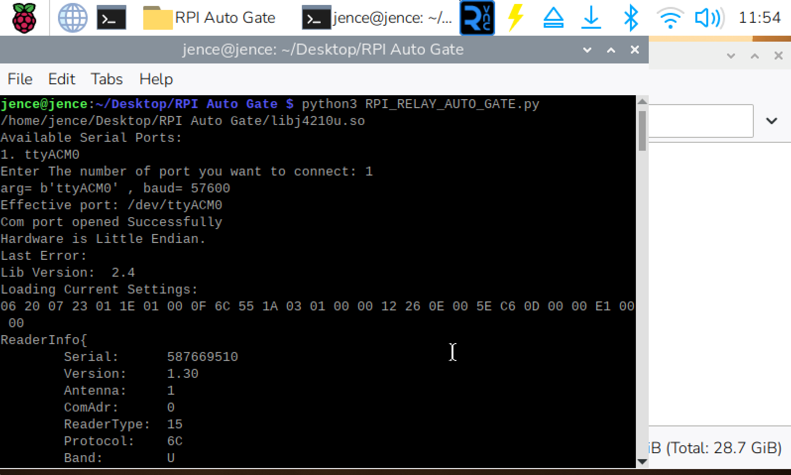
Script Execution Command
Navigate to your project directory in the terminal and launch the primary python controller:
cd ~/RPI_AUTO_GATE

python3 RPI_RELAY_AUTO_Gate.py
Interactive Serial Port Selection
Upon launch, the script scans available USB-to-Serial interfaces connected to the system. It displays an interactive terminal menu:
/home/pi/RPI_AUTO_GATE/

Available Serial Ports:

1. ttyACM0 (JENCE UHF Reader)

2. ttyUSB0 (Generic USB-Serial)

Enter the number of the port you want to use: 1
- Enter 1 (or the index matching ttyACM0 or ttyUSB0) and press Enter.
- The script establishes a serial link at the default baud rate (115200 for J4220U / 57600 for J4212U)[You need to hardcode the baud rate according to the reader you are using currently].
- The script immediately sends an initialization command setting GP01 to LOW (0), guaranteeing that the gate relay is forced into a safe, de-energized state.
Hardware Behavior Note (Power-On GPO State): When the JENCE reader is first powered on or plugged into USB, its onboard GPO pin may default to an uninitialized random state—frequently coming up HIGH upon cold boot. This may cause the relay’s indicator LED or coil to temporarily trigger when power is first applied. This is expected hardware startup behavior. As soon as you launch RPI_RELAY_AUTO_Gate.py in the terminal and select the port, the script immediately overrides the pin output state to LOW (0), resetting the relay and maintaining normal locked operation.
Step-by-Step Program Execution Logic
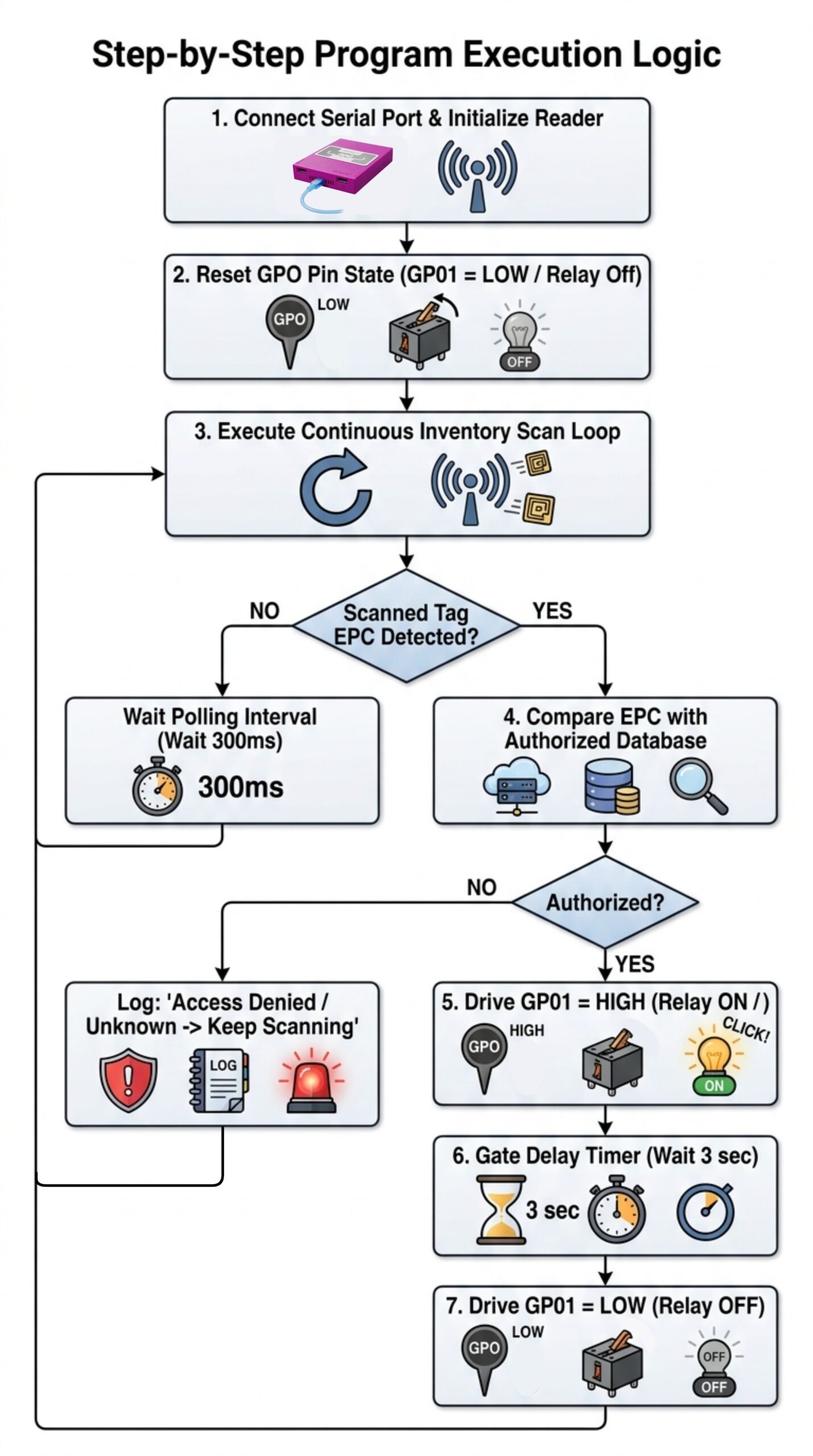
Complete Program Execution Logic Flowchart
- Continuous Inventory Scan: The Python script calls Inventory() in an infinite loop, constantly querying the JENCE reader’s RF field for passive UHF tags.
- EPC Data Parsing: When a vehicle mounted with an RFID windshield tag enters the antenna beam, the reader decodes the tag’s 96-bit EPC memory bank and transmits it over USB.
- Authentication Check: The script cross-references the scanned EPC/ string against an internal Python list containing authorized hex values (e.g., 3030AFEC2B09C44000000001).
- Relay Activation:
- If a match is verified, the terminal prints an authorization log message.
- The script calls SetGPO(1, 1) via j421xlib.py.
- GP01 output switches to 5V HIGH, sending current to the relay coil.
- Physical Gate Action:
- An audible mechanical “Click” echoes from the relay as its contacts close.
- The green status LED on the relay module lights up.
- High-current power flows from the external supply across the relay terminals to the DC motor, spinning the motor to simulate barrier gate lifting.
- Automatic Close Reset:
- The script executes a timed delay (e.g., time.sleep(3.0)).
- The script issues SetGPO(1, 0), returning GP01 to LOW.
- The relay opens, stopping the motor and closing the gate.
- The system immediately resumes scanning for subsequent vehicles.
Terminal Real-Time Logging & Output Verification
SCAN with No Tag Read
Scan and Tag Read, Triggering GPO
When executing live in the terminal environment, RPI_RELAY_AUTO_Gate.py outputs real-time diagnostics reflecting the inventory scanning cycle and relay control states.
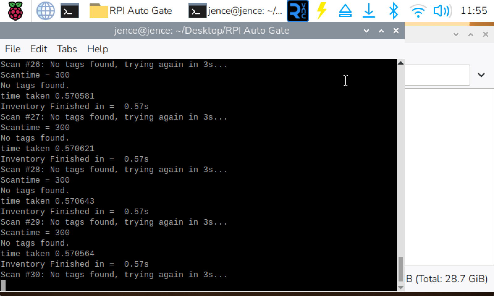
A. Idle Scan Loop (No Tags Detected)
When no UHF RFID tags are present in the reader’s RF coverage zone, the script completes inventory sweeps at set intervals (e.g., every 3 seconds) and prints diagnostic scan metrics:
Scantime = 300
No tags found.
time taken 0.570512
Inventory Finished in = 0.57s
Scan #17: No tags found, trying again in 3s...
Scantime = 300
No tags found.
time taken 0.570488
Inventory Finished in = 0.57s
Scan #18: No tags found, trying again in 3s...
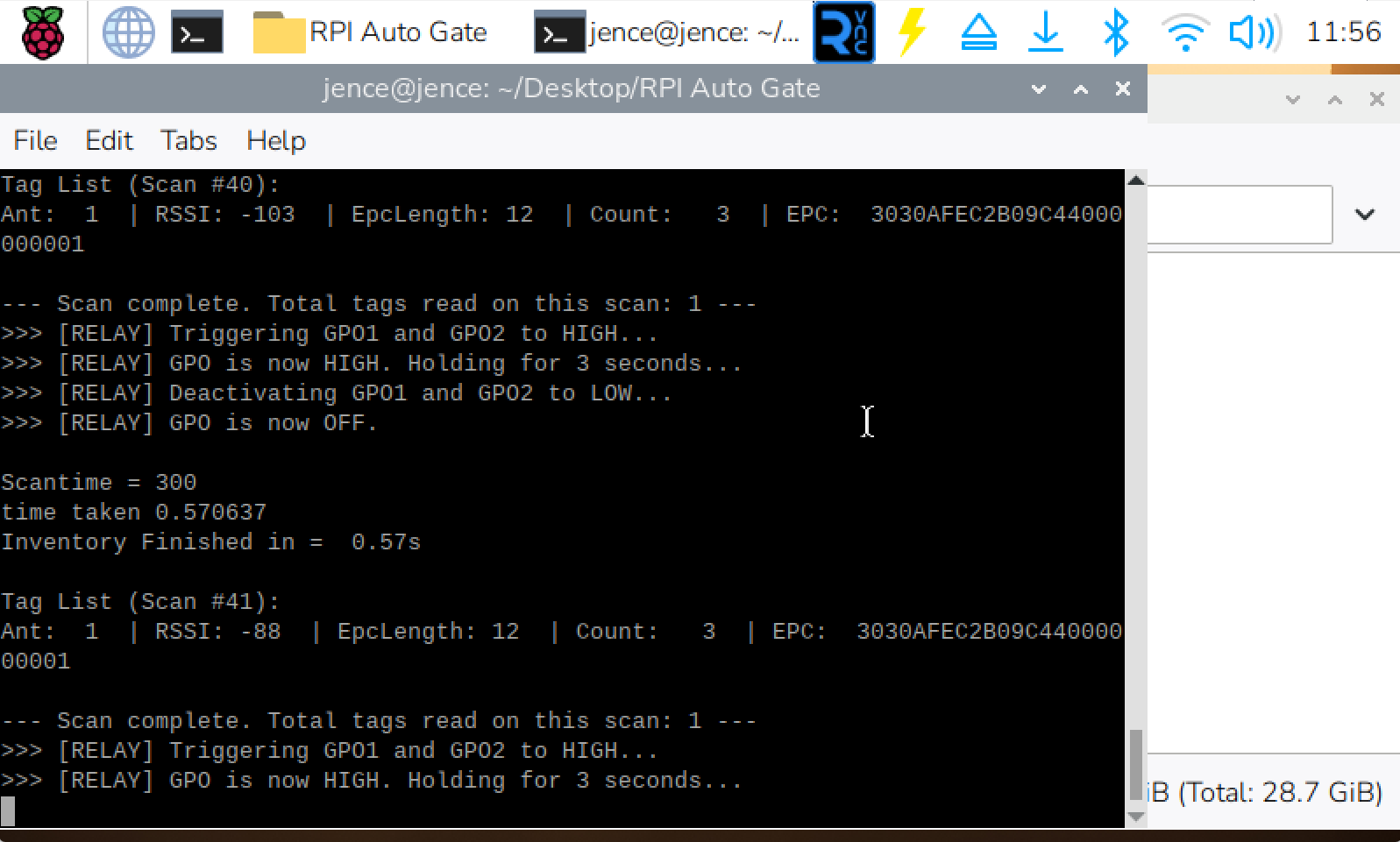
B. Tag Detected and Relay Activation Loop
When an authorized tag (e.g., EPC 3030AFEC2B09C44000000001) enters the antenna field, the terminal immediately logs the antenna channel, RSSI signal strength, EPC length, tag count, and executes the GPO trigger commands:
Tag List (Scan #4):
Ant: 1 | RSSI: -121 | EpcLength: 12 | Count: 3 | EPC: 3030AFEC2B09C44000000001
--- Scan complete. Total tags read on this scan: 1 ---
>>> [RELAY] Triggering GP01 to HIGH...
>>> [RELAY] GPO is now HIGH. Holding for 3 seconds...
>>> [RELAY] Deactivating GP01 to LOW...
>>> [RELAY] GPO is now OFF.
Inventory Finished in = 0.57s
Troubleshooting & Field Deployment Tips
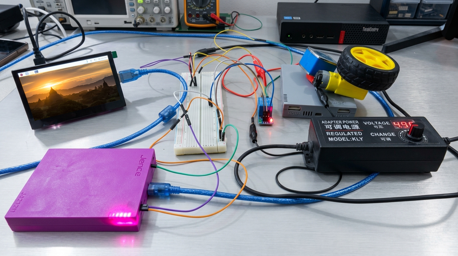
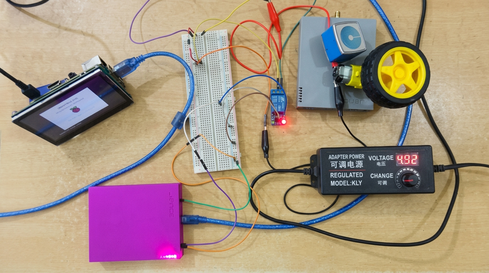
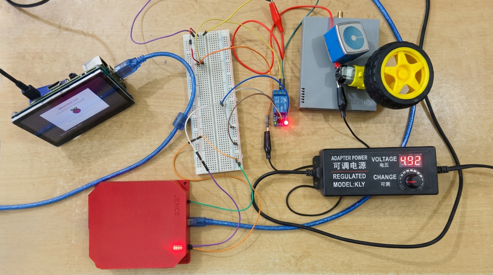
- Initial Boot Relay Flash / Click: As noted above, if the relay activates immediately upon plugging in the reader’s power, this is due to the hardware’s random power-up state (floating/HIGH). Running the Python application immediately clears this state by pulling GP01 LOW.
Serial Port Device Paths & Permissions (Permission Denied): Depending on Linux system permissions or OS configurations, serial devices are mounted under /dev/ (such as /dev/ttyACM0 or /dev/ttyUSB0). If your Raspberry Pi throws an AccessDenied error when opening the port, grant dialout group permissions to the current user:
sudo usermod -a -G dialout $USER
(Note: Log out and back in for group permissions to take effect).
- Unstable Motor Spinning / Pi Resetting: If the Raspberry Pi reboots or freezes when the motor starts, you are experiencing voltage drop caused by shared power rails. Ensure the motor is powered completely from an independent external power supply and that a flyback diode is installed.
- Relay Stays On Continuously: Verify your relay board’s trigger logic (Active High vs Active Low). If using an Active Low relay board, invert the logic in RPI_RELAY_AUTO_Gate.py so SetGPO(1, 0) activates the relay and SetGPO(1, 1) turns it off.
- Antenna Tuning for Gate Range: Adjust the JENCE reader power setting (0–26 dBm) in the configuration parameters within j421xlib.py to calibrate tag detection distances from 1 meter (personnel turnstiles) up to 10+ meters (vehicle boom gates).
Transforming Secured Access With Raspberry Pi and JENCE UHF Readers
Implementing an automated secured entry system with the Raspberry Pi and JENCE UHF RFID Reader is a strategic leap into frictionless modern automation. By replacing manual credential checking with radio frequency identification technology, you eliminate tailgating vulnerabilities, Reduce authorized entry times, and protect your assets with a high-efficiency security perimeter.
Subscribe to our newsletter :
