Support Blog
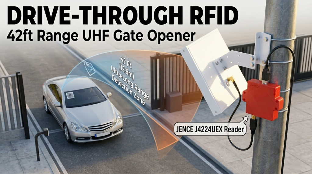
Build an Ultra-Long Range (42ft) Professional RFID “Drive-Through” with ESP32
Apr
Why settle for a gate that only opens when you’re inches away? This project utilizes the JENCE J4224UEX, a professional-grade UHF RFID reader capable of an incredible 42-foot (12.8m) range. Combined with the dual-core power of the ESP32, we’re building a system that identifies your vehicle while you’re still down the block, ensuring the gate is fully open before you even reach the driveway.
The Problem: The Short-Range Bottleneck
Most “automatic” gates aren’t actually automatic—they are manual triggers. You have to stop, roll down your window, and tap a card or wait for a 3-foot reader to wake up. This creates a bottleneck, especially in bad weather or high-traffic areas. If your gate takes 10 seconds to open, but your reader only sees you 2 seconds before you hit the gate, you’re stuck waiting every single time.
The Solution: “Full-Speed Long-Range” Access Control
By leveraging the JENCE J4224UEX, we move the detection zone back by nearly 13 meters. This allows the ESP32 to trigger the motor early. Using a professional MOSFET-driven relay circuit, we ensure the system is electrically isolated and safe, while the high-gain antenna of the J4224UEX handles the “eyes” of the operation.
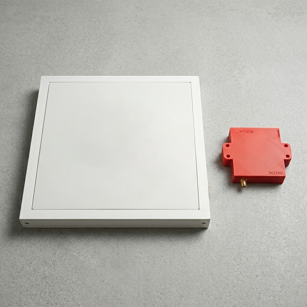
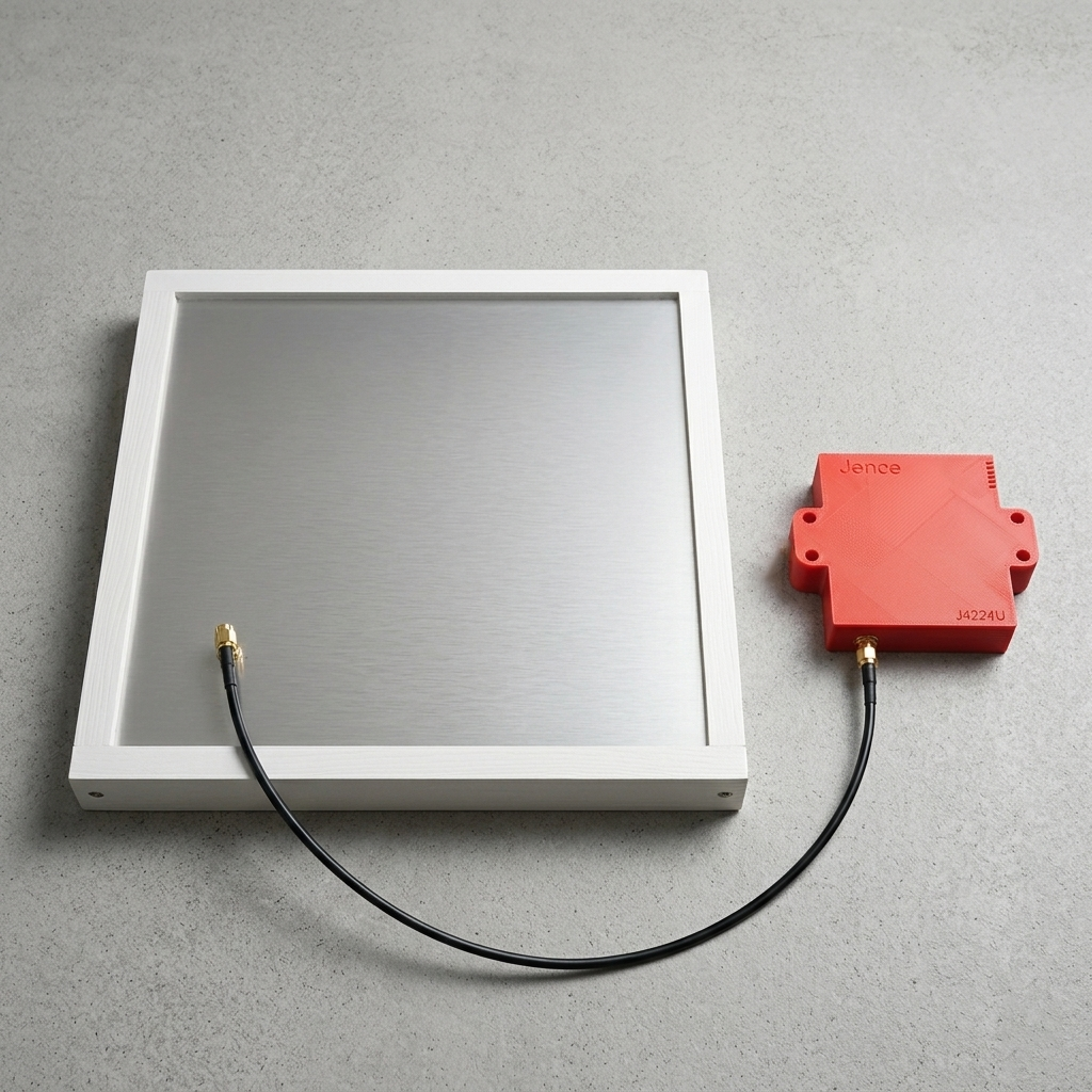
Figure 1: J4224 With Antenna Front View
Figure 2: J4224 with Antenna Connected Back view
Materials & Tools Required
|
Component |
Quantity |
Notes |
|
JENCE J4224UEX UHF Reader Writer |
1 |
Extended Range Reader/Writer |
|
ESP32 Development Board |
1 |
Any standard 30-pin board works well |
|
5V Relay Module |
1 |
To switch the gate control signal. 1 or 2 Channel |
|
Mosfet (CSD18532KCS) |
1 |
High-speed driver to protect the MCU |
|
Resistor (10 kΩ) |
1 |
Pull-down resistor for MOSFET gate stability |
|
Diode (1N4148) |
1 |
For motor back-EMF protection |
|
UHF RFID Tags (DogBone) |
3+ |
EPC GEN 2 (Use DogBone for max range) |
|
DC Motor |
1 |
Simulates the gate actuator (Works for AC as well) |
|
External 5V Power Supply |
1 |
Recommended for the Motor/Gate (Can Use both DC or AC power Supply) |
|
Hook-up Wires |
As needed |
Jumper wires (M-M, M-F, F-F) |
|
Breadboard (Optional) |
1 |
For prototyping the circuit |
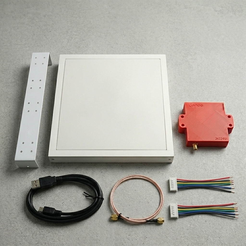
Figure 3: Jence J4224UEX Long Range UHF RFID Complete Product kit
Step 1: Prepare the ESP32 and Reader Hardware
The JENCE J4224UEX communicates via a standard UART (Universal Asynchronous Receiver/Transmitter) connection, to send the complex tag data. Meanwhile, the Relay Module uses a simple GPIO (General Purpose Input/Output) pin for an on/off command. Since the ESP32 has multiple UART ports, we’ll dedicate one (UART2) to the RFID reader.
1. The Power Grid:
-
- System Power: In this build, the ESP32 is powered via its USB port. Both the JENCE J4224UEX Reader and the Relay Module’s VCC receive their 5V power directly from the ESP32’s 5V pin. This keeps the logic side of the project simple and compact.
- Pro Tip: The J4224UEX requires a stable 5V. While the ESP32 can provide this via its 5V pin when powered by USB, it’s best to use an external 5V supply for the Reader to maintain that full 42-ft range.
- Common Ground: Every single component (ESP32, JENCE Reader, MOSFET, and Relay) must share a common Ground (GND). Without this, the UART data will become “noisy” and fail.
- External Power (The Muscle): An External Power Supply is used strictly for the motor circuit after the relay. The relay acts as a bridge, keeping the high-voltage motor power completely separate from the ESP32.
2. UART Communication (The Brains): Connect the J4224UEX’s UART pins to the ESP32:
-
- J4224UEX TXD → ESP32 RXD2 (GPIO 16)
- J4224UEX RXD → ESP32 TXD2 (GPIO 17)
- J4224UEX GND → ESP32 GND
- J4224UEX VEXT → ESP32 3V3 (set the logic level)
- J4224UEX 5V → ESP32 5V
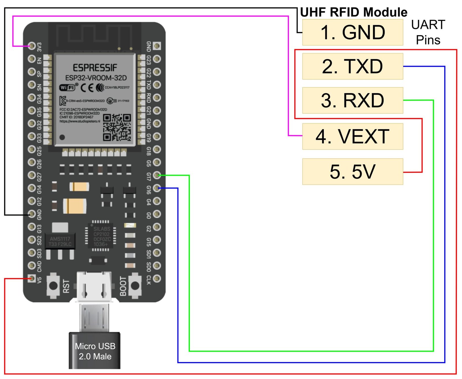
Figure-4: ESP32 wroom with J4224 pin connection
3. Relay & MOSFET Trigger Connection (The Switch): The ESP32 pins are delicate. To trigger a mechanical relay, we use a CSD18532KCS MOSFET. This protects the ESP32 from the relay’s current draw.
-
- Gate: Connect ESP32 GPIO 5 to the MOSFET Gate.
- Pull-down: Place the 10kΩ Resistor between the Gate and GND. This ensures that when the ESP32 is booting up, the gate doesn’t accidentally swing open.
- Drain: Connect the MOSFET Drain to the Relay “IN” pin.
- Grounding: MOSFET Source to the Relay GND and ESP32 GND.
- Relay Power: Relay VCC → ESP32 5V.
This setup uses the MOSFET as a high-speed switch to trigger the relay without putting strain on the ESP32’s pins. The relay acts as a switch for your gate motor.
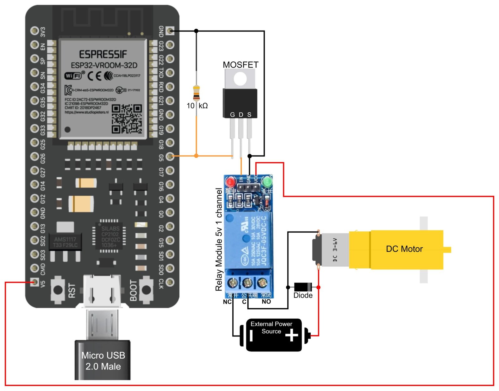
Figure-5: Mosfet and Relay Module Connection with ESP32
4. The Motor Load (The Muscle):
-
- DC Motor Setup: Connect the External Power Supply Positive (+) to the DC Motor. Connect the Negative (-) to the Relay’s Normally Closed (NC) port.
- Completion: Connect the Relay Common (COM) port to the other end of the DC motor.
- Protection: Place a Diode in parallel with the motor (Cathode to positive) to suppress voltage spikes (back-EMF) when the motor stops.
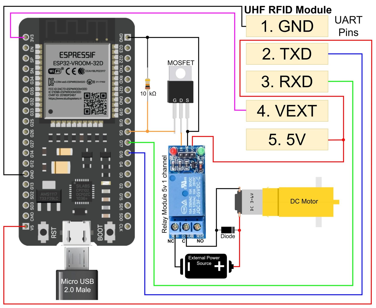
Figure-6: Complete Circuit Diagram of The Drive Through Automatic Gate Project
Wire Labeling:
-
The Power Tier (Red & Black)
-
-
Red Wire: Connects ESP32 5V to the J4224UEX 5V and Relay VCC.
-
Black Wire: Connects ESP32 GND to J4224UEX GND, Relay GND, and MOSFET Source.
-
Purple Wire (Optional): Used purple color for the VEXT (3.3V) line to distinguish logic voltage from supply voltage.
-
-
The Communication Tier (UART)
-
-
Blue Wire: “UART_TX” : From J4224UEX TXD to ESP32 RX2(GPIO16).
-
Green Wire: “UART_RX”: From J4224UEX RXD to ESP32 TX2(GPIO17).
Note: Remember that TX always goes to RX on the other side!
-
-
The Control Tier (Trigger)
-
-
Orange Wire: “GATE_TRIGGER”: From ESP32 GPIO 5 to the MOSFET Gate.
-
Orange Wire: “RELAY_IN”: From MOSFET Drain to the Relay Module “IN” pin.
-
-
The Motor Tier (Isolated Power)
-
-
Red Wire: “MOTOR_VCC”: From the External Power Supply to the Motor.
-
Black Wire: “MOTOR_RETURN”: From the Motor to the Relay COM/NC port.
Note: Remember to use a Diode to protect the Motor from Power Surge!
-
Note on Gate Wiring: The Relay Module functions as a basic switch. It must be connected to the trigger inputs of the gate control circuit (the same inputs utilized by an intercom button or a remote control receiver). Always refer to the gate system’s manual prior to wiring the relay to prevent any damage. Use the Relay’s Normally Open (NO) and Common (COM) ports. Both DC or AC components can be added after the relay.
Note on Versatility: Because the relay isolates the circuits, you can use this same logic for DC or AC motors. While this setup uses a 1-channel relay for one-way movement, upgrading to a 2-channel relay allows for bi-directional control (opening and closing).
USB Serial for Debugging [Optional]: The ESP32 employs its main USB-Serial interface to communicate with your PC, specifically the Serial Monitor in the Arduino IDE. This connection is essential for debugging purposes. It enables you to view messages, such as the confirmation “Authorized Tag Detected” when a tag is scanned or when the gate signal is activated. To facilitate this while also interacting with the JENCE J4224UEX reader, your MCU needs to operate two distinct UART ports: one dedicated to the PC/debugging and another for the JENCE J4224UEX reader. This dual configuration is advised for streamlined development.
Step 2: Configure and Test the RFID Tags
Before setting up the gate logic, you need to know the unique EPC (Electronic Product Code) of the tags you want to authorize.
- Software Download: Download the open-source SDK and Demo App from the JENCE GitHub repository: GitHub – jence/j4210u-app
- Initial Scan: Connect the J4224UEX directly to your PC (Windows, Mac, or Linux) using the provided USB cable.
- Run the Demo: Use provided demo application. J4210u-app-3.0.0platform”Your Operating System”/j4210u.exe
- Identify Tags: Scan your RFID tags (stickers or inlays). The software will display a list of all detected tags and their unique EPC values (usually a long hexadecimal string).
- Authorization List: Copy the EPC values of the tags you want to authorize (your car’s tag) into a text file. You can then hardcode these values into the ESP32 program.
Step 3: Configuring the 42-ft Detection Zone (Range Logic)
With a range this large, you don’t want to authorize every tag the reader sees (like a car parked in the neighbor’s driveway). We need to identify your specific “DogBone” tags.
- The Scan: Use the j4210u.exe demo. Place your vehicle tag 30-40 feet away.
- Adjusting Power: The J4224UEX allows power settings from 0 to 26dBm. For the full 42-ft range, set it to 26dBm. If the gate opens too early, you can dial it back to 20dBm in the software.
Step 4: Program the ESP32 (Authorization Logic)
The ESP32 firmware will now execute three main functions: listen for the reader, verify the tag against the “Allowed” list, and activate the MOSFET/Relay. While you might possess a robust testing program, for this step, we will focus on the essential C++ logic implemented with the Arduino framework for the ESP32, using the JENCE Arduino API.
- Include Libraries: You will need the appropriate JENCE Arduino API (C++) library for the reader.
#include <J4210U.h>
#include <Arduino.h>
- Define Constants: Set UART communication pins and GPIO Relay pin and baud(C++)
#define RXD2 16
#define TXD2 17
#define RELAY_PIN 5 // MOSFET Gate Trigger
#define UHF_READER_BAUD 57600
- Define Authorized Tags: Paste the EPC values copied in Step 2 into an array. (C++)
const char* authorizedEPCs[] = {
“E2801190200051187E26CB52”, // Example Tag 1 (Your Car)
“E2801190200051187E26CB53”, // Example Tag 2 (Family Member)
“E2002083980B01320390E6EB”, // Example Tag 3 (Used in this Project)
};
const int numAuthorizedEPCs = sizeof(authorizedEPCs) / sizeof(authorizedEPCs[0]);
- The Logic: The program follows a specific loop to ensure secure and consistent access:
- Initialization: During setup(), the ESP32 initializes Serial2 (pins 16 & 17) and configures the reader settings (like scan time and the buzzer).
- Inventory Scan: In the loop(), the code triggers an uhf.Inventory() scan to see all tags currently in the 42-foot range.
- Comparison: The code converts the raw tag data into a Hex string and checks it against the authorizedEPCs list.
- Trigger: * Match Found: The ESP32 sets CONTROL_GPIO to LOW. This triggers the MOSFET and clicks the relay to open the gate.
- No Match: The pin remains HIGH, keeping the gate closed.
- Interval: The system waits 3 seconds between scans to prevent the relay from “chattering” or triggering too many times in a row.
- Upload Code: Use the Arduino IDE with the ESP32 board package installed. Ensure you have selected the correct COM port and “ESP32 Dev Module” as your board before clicking upload. You can download the full code here: continuous_scan.zip
Step 5: Final Installation and Testing
- Strategic Mounting: Secure the J4224UEX at a height of 6–8 feet. Tilt the reader downward at a 20° angle toward the lane. This ensures the signal hits the vehicle’s windshield tags exactly where they are most visible with a clear line of sight.
- Power Delivery: Connect the ESP32 to a stable USB source. Ensure the JENCE reader pulls its 400mA from a dedicated high-current terminal to maintain its maximum range.
- Isolated Load: Verify your gate motor uses an independent power supply. The Relay acts only as a “dry contact” switch to trigger the gate’s controller.
- The “Drive-Through” Test: Start your test from 50 feet away. As you drive toward the gate, the reader should pick up the tag and trigger the motor while you are still 40 feet out. By the time you reach the entrance, the gate should be fully open for a “no-stop” experience.
Next Level Upgrades
- Bi-Directional Gate Control (2-Channel Relay): As previously mentioned, our current setup uses a 1-channel relay to trigger a gate to open. By upgrading to a 2-channel relay module or using a second relay, you can control the motor in both directions. This allows the ESP32 to send one signal to “Open” the gate and a second signal to “Close” it, or even reverse the polarity of the motor to wind the gate back.
- Remote Management: Use the ESP32’s Wi-Fi to sync with a JSON-based database. This allows you to add or remove authorized tags via a web dashboard without ever touching the hardware.
- Vehicle Safety and Auto-Close Sensors: Enhance safety by adding two IR sensors across the gate opening. Allowing the system to know exactly when the car has fully passed through the gate, ensuring that the system ignores “Close” commands if a vehicle is detected in the swing path. This prevents accidents from premature closing.
- Security Logging: Use an SD Card module or Firebase to log every entry attempt. Get instant mobile alerts if an unauthorized tag is detected near your property at night.
Troubleshooting Guide:
|
Issue |
Likely Cause |
Solution |
|
Short Range |
Low Power Setting |
Use the JENCE Demo software to increase power to 26dBm. |
|
Relay Chattering |
Rapid Tag Reads |
Increase the “Cooldown” interval in your code to 5+ seconds. |
|
No Detection |
Logic Level Mismatch |
Ensure the VEXT pin is connected to the ESP32’s 3.3V pin. |
|
False Triggers |
Floating Gate Pin |
Verify the 10kΩ Resistor is pulling the MOSFET Gate to GND. |
|
Reader Resetting |
Current Spikes |
Move the JENCE reader to a dedicated 5V/2A power source. |