Support Blog
Interfacing the J4212 and J4220 UHF Readers via USB to UART(TTL) Guide: Direct PC Interfacing
Nov
Introduction
While connecting an RFID reader to a microcontroller (like an Arduino or ESP32) is excellent for embedded projects, sometimes you need to connect the device directly to a PC. This allows for easier debugging, performance testing, or running powerful desktop applications without the limitations of a microcontroller.
This guide will walk you through interfacing the J4212 and J4220 UHF RFID Readers directly with your computer using a USB-to-TTL Serial Module.
Hardware Description
To establish a connection, we need a bridge between the UHF Reader (which uses UART logic) and the PC (which uses USB). For this, a USB to UART module is required.
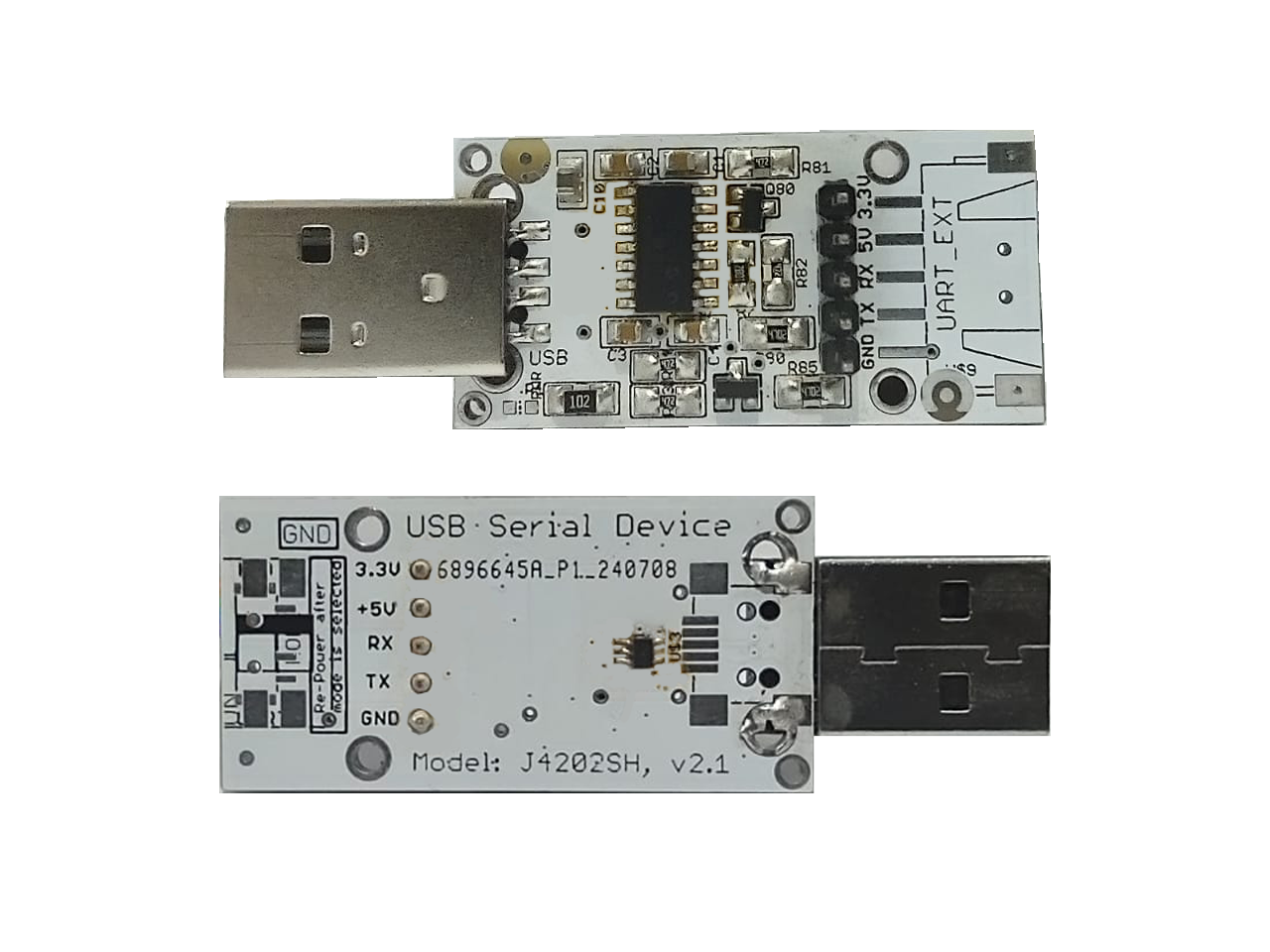
Note on Modules: There are many USB to UART modules / USB Serial Devices available on the market. As long as the module has the necessary 5 pins (5V, GND, 3.3V, TX, RX) and supports sufficient current, it will work. In this guide, we are using our own J4202SH USB Serial Device as an example.
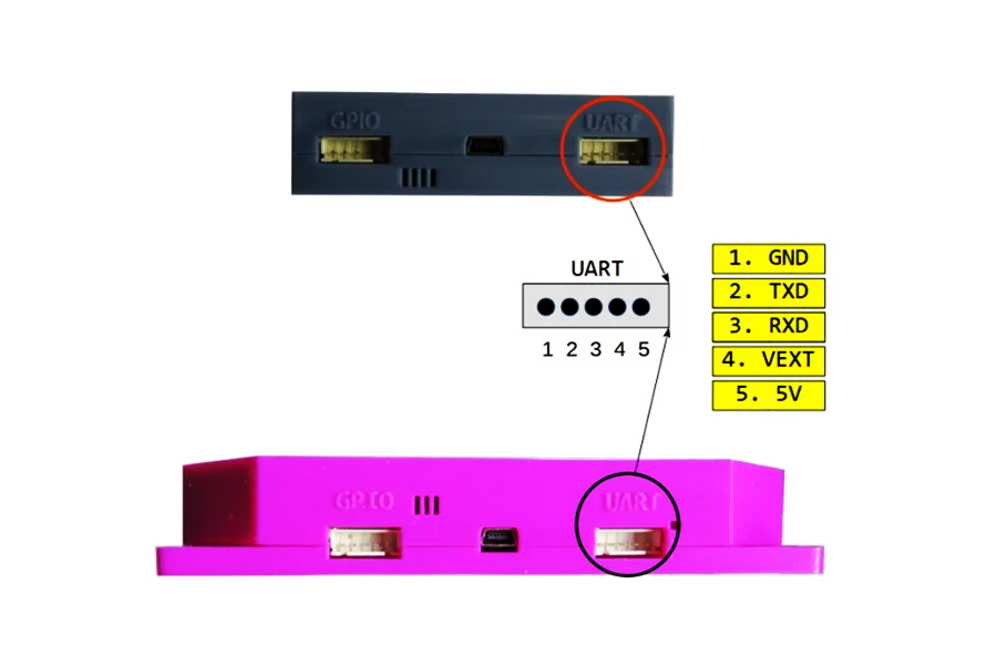
Pin Definitions
Regardless of the converter used, the connection requires specific pins to handle power & data.
| Pin Name | Description |
|---|---|
| 3.3V | Logic Reference Voltage. Connect this to VEXT on the reader. |
| 5V | Supply Voltage. Connect this to 5V on the reader. |
| RX | Receive Pin. |
| TX | Transmit Pin. |
| GND | Common Ground. |
Hardware Setup
Wiring Connection
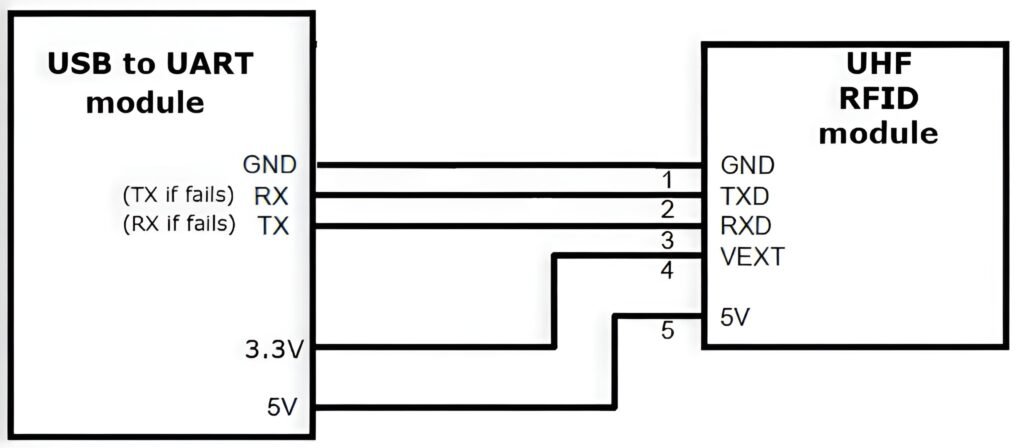
The USB to UART module connects to the computer via the USB port. You will need to use jumper wires to connect the 5 pins from the module to the J4212 and J4220 Readers.
The Connection Logic (RX/TX):
Standard UART communication requires a “Cross-Over” connection (TX connects to RX). However, labeling on different PCBs can sometimes vary or be confusing.
- Primary Method (Cross-Over): Connect TX to RX and RX to TX.
- Alternative Method (Straight): If the device does not respond with the primary method, try connecting TX to TX and RX to RX.
Wiring Table:
| UHF Reader Pin (J4212 and J4220) | USB to UART Module Pin | Note |
|---|---|---|
| 5V | 5V | Powers the reader (Reader requires ~400mA). |
| GND | GND | Common ground. |
| VEXT | 3.3V | Crucial: Sets the logic high level. |
| TXD | RX (or TX if fails) | Signal line. |
| RXD | TX (or RX if fails) | Signal line. |
Important: Ensure the VEXT pin on the reader is connected to the 3.3V pin on the module. Without this, the data lines have no logic reference, and communication will fail.
Software Installation & Usage
For these readers, we do not use generic terminal apps. Instead, we used our own dedicated open-source SDK software that supports multiple platforms (Windows, Linux, macOS, Raspberry Pi, etc.).
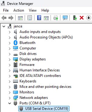
1. Driver Installation
For most modern PCs and standard USB to UART modules, the device is plug-and-play.
- Plug your USB to UART module into the PC.
- Open Device Manager and look under “Ports (COM & LPT)”.
- You should see a “USB Serial Device” or similar with an assigned COM port (COM19).
2. Download the Application
- Go to the GitHub release page: https://github.com/jence/j4210u-app/releases/tag/v3.0.0
- Click on Source code (zip) to download the file j4210u-app-3.0.0.zip.
- Extract the downloaded folder.
3. Run the Software
There is no installation wizard. Simply run the executable (.exe) for your specific OS from the extracted files.
- Navigate into the folder: j4210u-app-3.0.0platform.
- Open the folder matching your system (In this guide, we used win64 for 64-bit Windows).
- Run the executable (j4210u.exe).
4. Connecting and Scanning
Once the software is running:
1. Port: Select the COM port corresponding to your USB converter (COM19).
2. Baud: When configuring the readers, set 57600 for the J4212 and 115200 for the J4220.
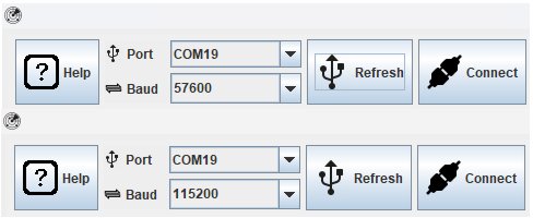
3. Click Connect.(If does not connects, Refresh, then Connect again)
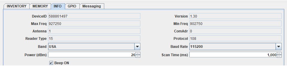
4. Go to the Info tab to verify If Device ID is visible. If yes, then it’s properly connected.
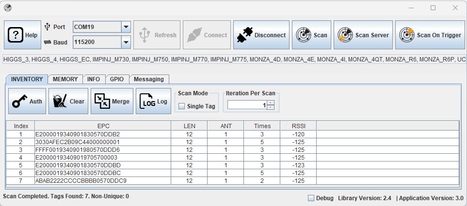
5. Go to the Inventory tab and click Scan (single scan) or Scan Server (continuous scan every 3 seconds).
Common Troubleshooting Tips
1. Communication Failure?
This is an issue that occurs when the Device Manager shows that the COM port is connected, the UHF RFID device receives power and has turned on but no data is going through. Resulting in a Failed to connect state.
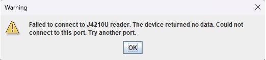
- Check RX/TX: As mentioned in the hardware setup, labeling can be tricky. If Standard Cross-Over (TX-RX) doesn’t work, try swapping them to a Straight Connection (TX-TX / RX-RX).
- Check VEXT: Double-check that VEXT is connected to 3.3V.
2. Device keeps disconnecting?
This is rarely an issue with the USB connection itself. It is usually caused by loose jumper wires.
- Ensure the female headers on your jumper wires are tight and not wobbly.
- Verify the physical connection between the USB converter pins and the UHF Reader pins is solid.
3. The reader is scanning but no tags appear?
- Ensure the reader is getting enough power (5V pin connected).
- Check that you are using the correct region settings in the software for the tags you are using. Verify that tags are correctly positioned on the side of the device with the antenna.
Heard some buzz about the new UART interfacing guide. Gonna check it out, maybe it’s the solution for our PH-based logistics project. Hoping for high-speed scanning and fast data output!
The RFDOME open-source software is my go-to for custom implementations. Keeps my dev cycle smooth for hours. Data throughput is consistent and gameplay—I mean, API response—is very smooth. Highly recommend!
Has anyone tested the J4220 for long-range industrial tracking? Tell me your experience, mate. Looking into these UHF readers for a warehouse automation project.
Sorted out my USB to UART bridge finally! The driver installation for the J4212 was smooth as butter. Let’s see what kind of data throughput we can get on the serial monitor. Highly recommended if you are keen on RFID systems!
If you’re looking for some high-performance UART interfacing tips, check out the J4212 and J4220 documentation. I found some amazing open-source RF software there; give it a shot if you need a direct PC-to-reader connection.
Just had a look at the UART TTL communication protocols for the J4212. The data frame structure is solid and simple to integrate. If you need a stable PC to UHF reader interface, this guide is a great starting point for your serial port configuration.