Support Blog
How to drive a linear motor using J4220, J4212, and J4224 UHF readers with a GPIO port.

Jan
Hardware Description
UHF Module
| Pin Name | Type | Potential Description |
|---|---|---|
| I1 | Input |
Digital Input 1: General Purpose Input pin.
Can be controled with UHF driver library of a MCU or PC DLL library with unsigned char GetGPI(unsigned char gpino); function.
|
| I2 | Input | Digital Input 2: Same as I1. |
| GND | Ground | Ground (0V): Ground Pin. |
| O1 | Output |
Digital Output 1: General Purpose Output pin. Can be controlled with UHF driver library of a MCU of PC DLL library with
unsigned char SetGPO(unsigned char gpono);
function.
|
| O2 | Output | Digital Output 2: Same as O1. |
Motor Controller
| Pin Name | Type | Potential Description |
|---|---|---|
| Input | Input [Power] | 12V-24V DC (Ensure correct polarity: Positive (+) and Negative (-) Terminals) |
| Output | Output [Power] | Connection Terminals for Motor |
| GND | Ground | Ground Pin. |
| DIR | Input [Logic] | This pin is responsible for changing direction of the motor. |
| EN | Input [Logic] | This pin is responsible for enbling the motor. |
| 5V | Input [Logic] | This pin take input of 5 volts for logic in isolated mode. |
| NC | No Connection | There is no connection in this pin. |

Hardware Setup:
Connection Basic:
There are two modes: 1. Isolated Mode 2. Common ModeFor Isolated Mode:
- Connect O2 with DIR of controller.
- Connect O1 with EN of controller.
- GND with GND.
- 5v port with 5 of controller.
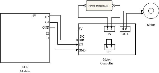
For Common Mode:
-
Connect O2 with DIR of controller.
-
Connect O1 with EN of controller.
-
GND with GND.
- Sort the JP1 Pins on the Controller
Power Requirements:
The motor controller requires a 12V DC power supply. It is crucial to observe correct polarity when connecting the power supply to the input port: positive (+) to positive and negative (-) to negative. Connect the linear actuator to the controller’s output port.
Demo
To begin the demo, follow these steps:
-
Download the demo software from our Github Repo, choosing the version for your platform.
-
Connect the UHD module to your computer using a USB cable.
-
Open the downloaded application and select the correct communication port for the UHD module.
-
Establish the connection with the module.
-
The available GPIO interfaces are shown below:

After connecting the controller with the UHF module. The UHF module is connected to a PC and controlled through our demo software. When GPO1 is set it will trigger the Forward of Linear Actuator as shown in above. When both GPO is set(Ticked) is should trigger the Reverse of Linear Actuator which shown in below.

Interesting read! Considering the voltage levels and timing is key when driving linear motors. Seeing hardware like the J4220 focus on precision GPIO control is a smart move for automation projects. Managing the logic thresholds definitely helps long-term stability! Great technical insights here.
Interesting points about adapting the GPIO strategy! Using automation tools for hardware testing really changes the development workflow – speed and accessibility are key, especially when testing linear motor responses with UHF readers. It’s a game changer for industrial automation.
Been messing around with the J4220 GPIO ports and the signal stability is on point. Support team was very helpful when I had a question about the pinout. Good selection of SDKs.
Setting up the GPIO triggers was super simple with this guide. No more configuration headaches! Plus, the reader’s response time is excellent. Check the status LED logic if you’re stuck.