Support Blog
Getting Started with the J4210 UHF RFID Reader-Arduino Interfacing: A Complete Guide
Feb
Introduction
Are you looking to integrate a powerful UHF RFID reader into your projects? The J4210 UHF RFID Reader is a great choice for developers, system integrators, and tech enthusiasts who want an efficient and versatile RFID module. This guide will walk you through everything you need to set up and use the J4210 with popular microcontrollers like Arduino, ESP32, and Raspberry Pi Pico.
Hardware Description
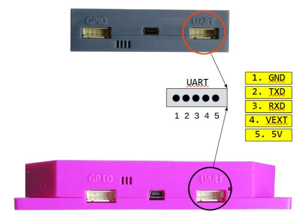
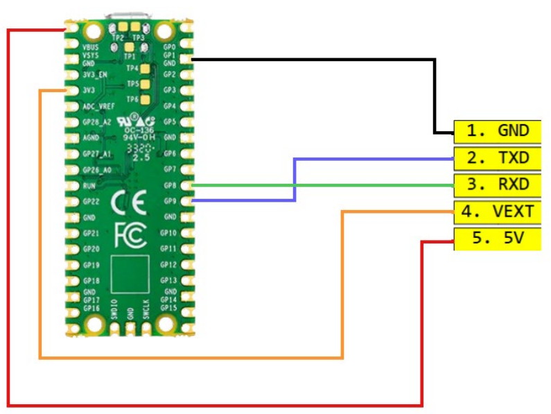
The J4210 RFID Reader supports both USB and UART communication interfaces. The UART interface allows direct communication with microcontrollers via RX and TX pins.The configuration picture is given below
| UART | RXD and TXD will be crossed with the MCU’s TXD and RXD. |
|---|---|
| VEXT | This is the Logic High, VOH voltage. In 3.3V logic, tie it to 3.3V; in 5V logic, tie it to 5V. |
| 5V | This is supply voltage. Do not supply 3.3V here. |
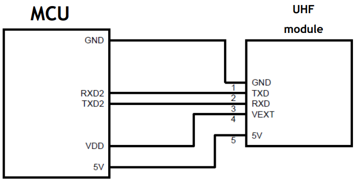
The basic idea is to connect the uhf reader module with an MCU like below configuration
Hardware Setup
Connection Basic
The key is MCU needs 2 sets of UART port. One is to connect with the PC through USB-Serial device to monitor the status of the MCU through Serial Monitor. Another set of UART is to communicate with the module to send command and retrieve information. In the example, we are using UART2 for the Module – MCU communication but it is configurable as the user wants.Only 1 set of UART pins can do the communication if Serial Monitor is not needed. Our example uses 2 sets of UART port.
Power Requirements
UHF RFID Module requires 400mA, 5V power while scanning. If the MCU is used as power source for the module it will take around 400mA of current while scanning. While scanning if the MCU can’t provide that much current then scan will fail. So, if the MCU can’t provide 400mA 5V then external power source is needed.
Connection Schemes for different Microcontrollers:
Connection configuration example for some common microcontroller that can be used with Arduino platform is provided below. Note that pin configuration is just an example and an expert user can configure their pins however they want reflecting their code.
For Arduino Mega:

FOR ESP32 dev module (wroom):

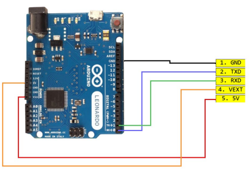
For Arduino Leonardo:
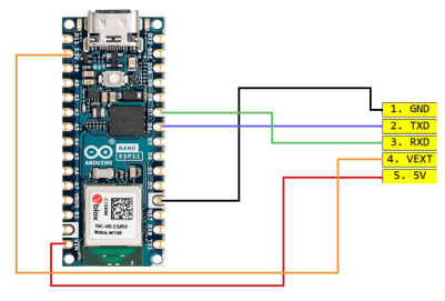
For Arduino Nano esp32:
For TivaC Launchpad with TM4C1294NCPDT:


For RPI Pico:
Software Installation:
UHF RFID readers has an Arduino framework library class named J4210U. In the J4210U.h file the public methods are to be used to communicate with the RFID reader. For the library class, some example sketch is also provided that does some operation to demonstrate some of the functionality of the library.
Software Setup
- Download, Install, and Setup Arduino IDE normally.
- Open Arduino IDE.
- In the menu bar, go to Sketch > Include Library > Add .ZIP Library…
- Select the bundled
j4210_driver_arduino_lib.zipfile in the file explorer prompt. - The library should install in the Output Terminal at the bottom.
- Restart the Arduino IDE.
- In the menu bar, go to File > Examples > j4210U Uhf RFID Reader Driver and choose one.
- You will find three examples—choose one to run and check its usage.
- Uncomment
// #define NANO_ESP32from the example sketches if using Arduino Nano ESP32. - Connect the wires accordingly based on the MCU.
- Configure Arduino IDE (or Code Composer Studio for TivaC board) for the correct MCU board configuration from the TOOLS tab.
- Build and upload the sketch.
- Check the Serial Monitor for messages. The default baud rate is 9600.
- If successful, the Serial Monitor will display example-specific output. For the continuous scan example, you will see the reader settings in the Serial Monitor. The reader will scan nearby UHF tags every 3 seconds, displaying the EPC and TID values.
- Once the examples are working, you can start using the library for standard applications like:
- GetSettings
- SetSettings
- Inventory Scan
- Read/Write
- Filter GPIO
- SetPassword
- Lock/Kill operations
Common Troubleshooting Tips
1. Device not responding?
Test the device with platform-specific desktop software before connecting it to an MCU.
2. Communication failure?
While connecting the wires sometimes Rx and Tx might get mixed up by mistake and
that can cause failed communication. Check if the Rx and Tx is connected properly and
try swapping the Rx and Tx.
3. Module not detecting tags?
Module is connected but scan can’t find any tags. It might be due to the module is not
getting enough power to scan. Connect an external power source with 5V and GND pin
4. Baud rate issues?
The default baud rate is 57600 bps. If communication fails, try setting it to 115200 bps.
5. Reader is scanning but no data appears?
VEXT is the logic voltage. If VEXT doesn’t get matched input voltage as the logic HIGH
level then the communication won’t work. Check the voltage level of VEXT
Wishing you happiness every day.
Looking forward to reading more from you.
Interesting points about balancing power & range in RFID setups! Seeing readers like the J4210 focus on sensitivity and stable Arduino interfacing is a smart move for developers seeking reliable data collection. Proper power management is key for long-range performance, always!
Just finished setting up the J4210 UHF RFID Reader with my Arduino! The interfacing is slick and the code provided here works perfectly. Let’s see if my read range reaches the maximum today. Placing my sensors in the field and hoping for a 100% success rate!